PRODUCT · Couplings
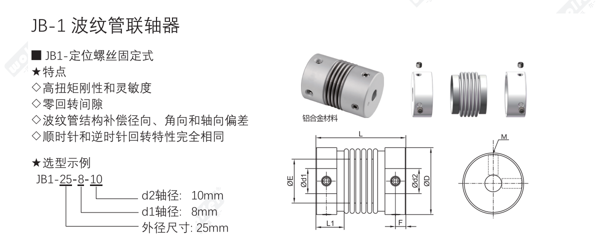
JB series bellows couplings: a metal bellows flexure with high torsional stiffness, zero backlash and high transmission accuracy, compensating misalignment in all three axes. For high-precision positioning, servo, metrology and semiconductor equipment.
Last updated Reviewed by Luo Genwen, Production Plant Manager
Coupling Selector · Specifications
Choose a series by its drawing, then view dimensions and performance separately. Search, use the declared filters, or sort by any column.
Choose a series by drawing
Select a drawing to load its matching data
Drawing view
Parameter category
Data table
| Model | Minimum bore dmin · mm | Maximum bore dmax · mm | Outside diameter D · mm | Overall length L · mm | L1 dimension L1 · mm | F dimension F · mm | E dimension E · mm | Set screw M | Tightening torque N·m |
|---|---|---|---|---|---|---|---|---|---|
| JB1-16 | 4 | 8 | 16 | 30 | 10.5 | 4 | 9.5 | M3 | 0.7 |
| JB1-20 | 6 | 12 | 20 | 33 | 12.5 | 4 | 12.5 | M3 | 0.7 |
| JB1-25 | 6 | 12 | 25 | 38 | 14 | 5 | 16 | M4 | 1.7 |
| JB1-32 | 8 | 14 | 32 | 43 | 13.5 | 5 | 21 | M4 | 1.7 |
| JB1-40 | 10 | 16 | 40 | 62 | 21 | 8.5 | 28 | M5 | 4 |
| JB1-55 | 12 | 19 | 55 | 72 | 23 | 7.5 | 38 | M6 | 7 |
| Model | Rated torque N·m | Maximum torque N·m | Maximum speed rpm | Moment of inertia kg·m² | Static torsional stiffness N·m/rad | Radial deviation mm | Angular deviation ° | Axial deviation mm | Mass g |
|---|---|---|---|---|---|---|---|---|---|
| JB1-16 | 0.8 | 1.6 | 20000 | 3.4×10^-7 | 100 | 0.1 | 1.5 | +0.3/-1.0 | 8 |
| JB1-20 | 1.5 | 3 | 15000 | 8.9×10^-7 | 160 | 0.1 | 1.5 | +0.3/-1.0 | 12 |
| JB1-25 | 2 | 4 | 13000 | 2.8×10^-6 | 220 | 0.15 | 2 | +0.5/-1.3 | 28 |
| JB1-32 | 2.5 | 5 | 10000 | 8.8×10^-6 | 310 | 0.2 | 2 | +0.5/-1.3 | 46 |
| JB1-40 | 10 | 20 | 8000 | 1.5×10^-5 | 520 | 0.2 | 2 | +0.5/-1.3 | 88 |
| JB1-55 | 25 | 50 | 6000 | 2.3×10^-5 | 850 | 0.2 | 2 | +0.7/-1.5 | 180 |
| Model | Minimum bore dmin · mm | Maximum bore dmax · mm | Outside diameter D · mm | Overall length L · mm | L1 dimension L1 · mm | F dimension F · mm | E dimension E · mm | Set screw M | Tightening torque N·m |
|---|---|---|---|---|---|---|---|---|---|
| JB2-16 | 4 | 8 | 16 | 30 | 10.5 | 4 | 9.5 | M3 | 0.7 |
| JB2-20 | 6 | 12 | 20 | 33 | 12.5 | 4 | 12.5 | M3 | 0.7 |
| JB2-25 | 6 | 12 | 25 | 38 | 14 | 5 | 16 | M4 | 1.7 |
| JB2-32 | 8 | 14 | 32 | 43 | 13.5 | 5 | 21 | M4 | 1.7 |
| JB2-40 | 10 | 16 | 40 | 62 | 21 | 8.5 | 28 | M5 | 4 |
| JB2-55 | 12 | 19 | 55 | 72 | 23 | 7.5 | 38 | M6 | 8 |
| JB2-65 | 18 | 38 | 65 | 81 | 25.5 | 8.5 | 45 | M8 | 15 |
| JB2-82 | 20 | 42 | 82 | 103 | 34.5 | 10.5 | 56 | M10 | 28 |
| Model | Rated torque N·m | Maximum torque N·m | Maximum speed rpm | Moment of inertia kg·m² | Static torsional stiffness N·m/rad | Radial deviation mm | Angular deviation ° | Axial deviation mm | Mass g |
|---|---|---|---|---|---|---|---|---|---|
| JB2-16 | 0.8 | 1.6 | 18000 | 3.4×10^-7 | 100 | 0.1 | 1.5 | +0.3/-1.0 | 8 |
| JB2-20 | 1.5 | 3 | 13000 | 8.9×10^-7 | 160 | 0.1 | 1.5 | +0.3/-1.0 | 14 |
| JB2-25 | 2 | 4 | 11000 | 2.8×10^-6 | 220 | 0.15 | 2 | +0.5/-1.3 | 32 |
| JB2-32 | 2.5 | 5 | 10000 | 8.8×10^-6 | 310 | 0.2 | 2 | +0.5/-1.3 | 52 |
| JB2-40 | 10 | 20 | 8000 | 1.5×10^-5 | 520 | 0.2 | 2 | +0.7/-1.5 | 98 |
| JB2-55 | 25 | 50 | 6000 | 2.3×10^-5 | 850 | 0.2 | 2 | +0.7/-1.5 | 200 |
| JB2-65 | 60 | 120 | 4500 | 2.8×10^-5 | 960 | 0.2 | 2 | +0.7/-1.5 | 350 |
| JB2-82 | 80 | 160 | 4000 | 6.0×10^-5 | 1290 | 0.2 | 2 | +0.7/-1.5 | 750 |
| Model | d1 minimum bore d1 min · mm | d1 maximum bore d1 max · mm | d2 minimum bore d2 min · mm | d2 maximum bore d2 max · mm | Outside diameter D · mm | Overall length L · mm | L1 / L2 L1/L2 · mm | E dimension E · mm | D1 dimension D1 · mm | D2 dimension D2 · mm | M1 screw M1 | M screw M | Tightening torque N·m |
|---|---|---|---|---|---|---|---|---|---|---|---|---|---|
| JB3-40T | 10 | 18 | 10 | 18 | 40 | 55 | 19 | 28 | 35 | 38 | M4 | M4x4 | 2.5 |
| JB3-55T | 12 | 23 | 12 | 23 | 55 | 65 | 22 | 38 | 42 | 52 | M5 | M5x6 | 4 |
| JB3-65T | 12 | 29 | 12 | 29 | 65 | 76 | 27 | 45 | 52 | 62 | M5 | M5x6 | 4 |
| JB3-82T | 15 | 38 | 15 | 38 | 82 | 87 | 32 | 56 | 70 | 78 | M6 | M6x6 | 8 |
| Model | Rated torque N·m | Maximum torque N·m | Maximum speed rpm | Moment of inertia kg·m² | Static torsional stiffness N·m/rad | Radial deviation mm | Angular deviation ° | Axial deviation mm | Mass g |
|---|---|---|---|---|---|---|---|---|---|
| JB3-40T | 10 | 20 | 6600 | 0.12×10^-3 | 8300 | 0.2 | 1 | 2 | 260 |
| JB3-55T | 25 | 50 | 6000 | 0.27×10^-3 | 12900 | 0.25 | 1.5 | 1.5 | 400 |
| JB3-65T | 60 | 120 | 5000 | 0.63×10^-3 | 21800 | 0.25 | 1.5 | 1.5 | 800 |
| JB3-82T | 130 | 260 | 4000 | 1.50×10^-3 | 48500 | 0.25 | 1.5 | 1 | 1200 |
Static copy of the selector data for reference and printing; use the interactive selector above to filter, sort and request a quote. All dimensions in mm; full range and tolerances per the PDF catalogue.
Dimensions and performance are shown separately. Sort by any column; consult the PDF catalogue for the full range, tolerances, and operating conditions. Download PDF catalogue ↗
FAQ
This page covers 3 series (JB-1, JB-2, JB-3-T) with 18 catalogue sizes: bores from Ø4 to Ø42 mm, rated torque 0.8–130 N·m. Finished bores, keyways and clamp variants are machined to your shaft; sizes outside the tables are made to drawing.
JB series bellows couplings: a metal bellows flexure with high torsional stiffness, zero backlash and high transmission accuracy, compensating misalignment in all three axes. For high-precision positioning, servo, metrology and semiconductor equipment. Bellows couplings give the highest torsional stiffness of the zero-backlash types, so they are used where positioning accuracy and dynamic response matter most: ball-screw drives, measuring machines, encoders and servo axes. They compensate all three kinds of misalignment but are not for shock or damping duty.
Yes. Everything on this page is made to drawing, and the table is only the standard-size subset of the catalogue. Minimum order quantity is one piece — we routinely make single replacement parts for OEMs whose original supplier has discontinued the item. Send a DWG, STEP or PDF drawing (or a sample part): you get a formal quotation within 24 hours after the information is complete, and the first article ships within 30 days of drawing approval, with inspection records.
Send: shaft diameters and lengths on both sides (with keyways or clamp preference), rated and peak torque, speed, the misalignment you expect (angular, radial, axial), space available (outside diameter and overall length), operating temperature and whether the drive is servo/positioning or general. A drawing or STEP of the two shaft ends is ideal; a sketch with these values is enough for a first quote.